Automatic line fault location
23 May 2025
AURA recorders provide single-ended line fault location based on steady-state fault quantities. Calculations cover all short-circuit types and take account of the following characteristics of the line and the fault:
- positive- and zero-sequence resistance and reactance per unit length for each line section, with any number of sections;
- one parallel line with mutual inductive coupling over the entire length or over a section extending from the near end;
- shunt capacitive admittance;
- taps on the main and parallel lines;
- infeed from both line ends;
- connections between the main and parallel lines at the local and/or remote end;
- resistive arc impedance at the fault location.
Fault location assumes a purely resistive fault (Qfault = 0) and equal per-unit-length parameters for the main and parallel lines. If the shunt capacitive admittance of a section is unspecified, it is calculated automatically from the assumed electromagnetic wave propagation velocity along the line.
The recorder uses precomputed per-unit-length parameters for the line sections. Calculation from conductor and tower geometry requires third-party software that is not supplied with the recorder.
The recorder uses precomputed equivalent impedances for line taps, including the tapped line, transformer and downstream load. An optional spreadsheet, “Расчёт параметров отпаек.xlsx”, contains formulas for the most common cases.
Line parameters are entered in the recorder’s web interface as shown below:
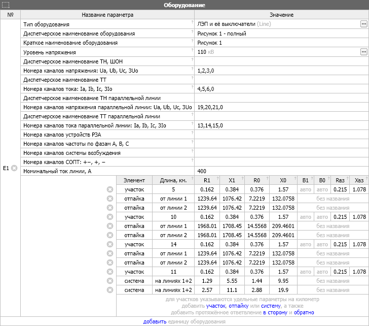
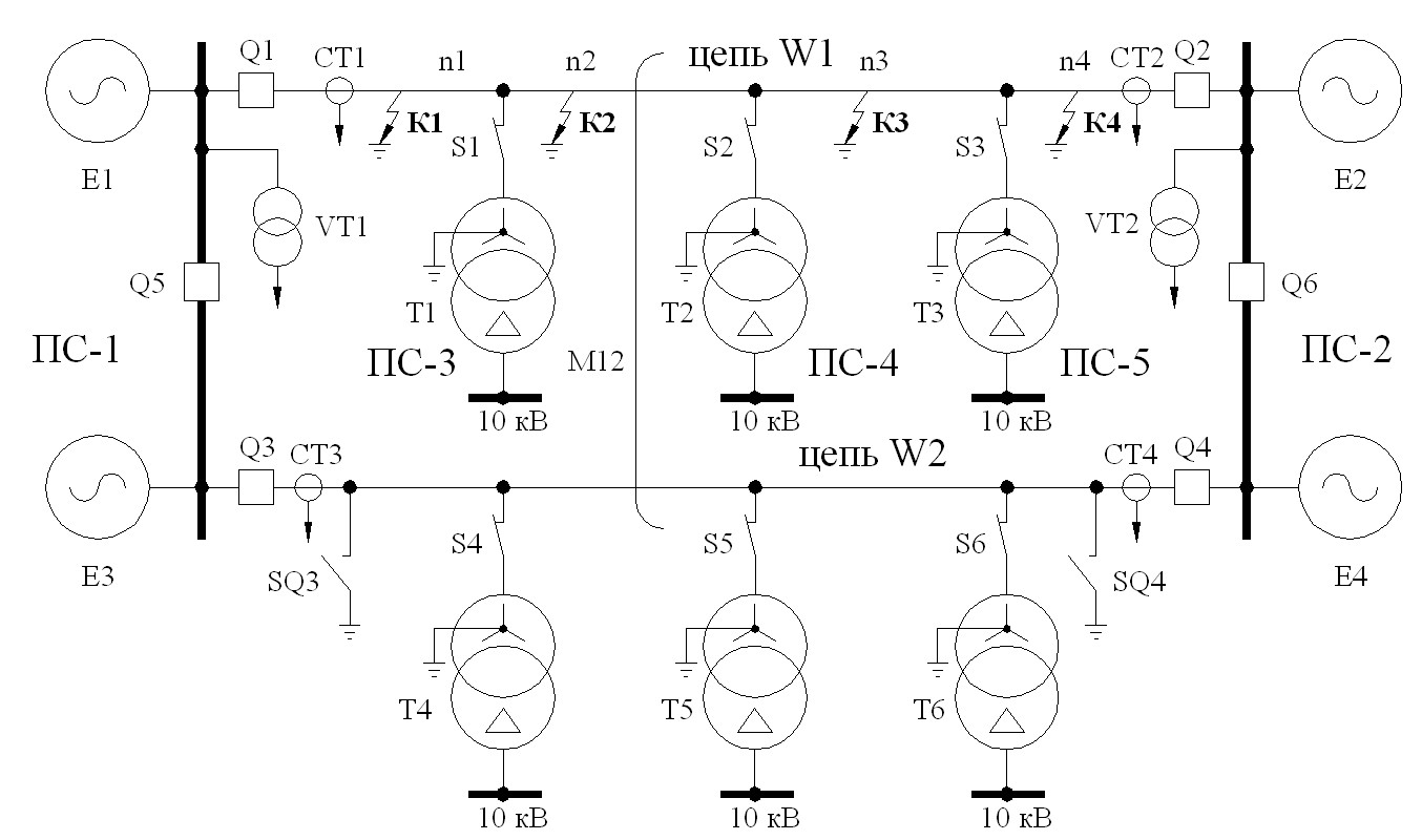
The diagram above shows one possible line arrangement. Below are a sample event report in human- and machine-readable text form and a screenshot of the recorder's web interface.
Record: 110 kV 20 km (of 40 km) A0 5 Ω(phase) 5 Ω(ground) 24-06-20 13-06-58
AuraQt: 1.2.8.5-ge06e5b7
LineNL: Figure 1 — complete
LineNS: Figure 1
Normal: 2024-06-20 13:06:58.000+05
Faulty: 2024-06-20 13:06:58.030+05 0.120 sec
Measur: 2024-06-20 13:06:58.120+05
Z0near: 0.156 + 2.255j
Z2near: 0.444 + 3.000j
Resist: Ra≈10
Digest: A0 trip
Distan: 20.05 of 40 km
Ua = 69.494 kV 12.82° Ia = 0.259 kA 14.35°
Ub = 69.494 kV −107.18° Ib = 0.259 kA −105.65°
Uc = 69.494 kV 132.82° Ic = 0.259 kA 134.35°
U1 = 69.494 kV 12.82° I1 = 0.259 kA 14.35°
U2 = 0.000 kV 105.63° I2 = 0.000 kA 155.86°
3U0 = 0.000 kV -68.32° 3I0 = 0.000 kA -140.58° (calculated)
Ua = 65.418 kV 8.99° Ia = 2.405 kA -19.56°
Ub = 68.352 kV -106.76° Ib = 0.261 kA -141.82°
Uc = 69.641 kV 131.79° Ic = 0.419 kA 139.13°
U1 = 67.772 kV 11.38° I1 = 1.001 kA −14.75°
U2 = 2.436 kV −122.87° I2 = 0.784 kA −24.01°
3U0 = 3.636 kV −114.56° 3I0 = 1.876 kA −21.65° (calculated)
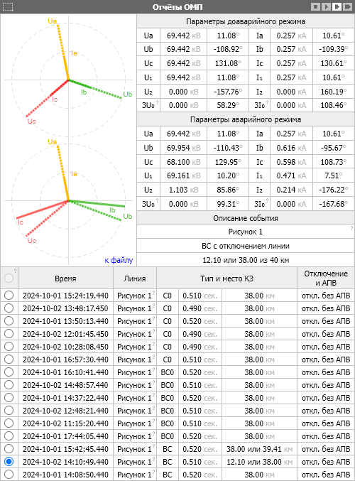
The recorder also includes fault location results in disturbance reports generated in accordance with GOST R 58601-2019.
The recorder's fault location function is being developed to meet Rosseti standard STO 34.01-4.1-001-2016 and tested using the corresponding procedure of the OP TsPS laboratory at JSC FGC UES R&D Center. Internal testing based on MATLAB Simulink models took place in 2024 and early 2025. Certification testing using RTDS is planned for 2025.